Implement a Network Service
Objectives
- Learn how to access Service Designer tool in Telco Network Cloud Orchestration (TNC-O)
- Create a new Assembly Descriptor working as a starting point for a new Network Service (NS) design
- Design the Network Service using the Designer
Pre-requisites
Before you begin following pre-requisites should be fulfilled:
- Access to TNC-O environment with applicable user role assigned to the user account (see Installation and Config of TNC-O for more details on user roles)
- Necessary Virtual Network Function (VNF) packages developed and onboarded to the TNC-O environment (see Develop a VNF package for more details)
- Used the LMCTL command to create the NS project and pushed that into the environment
Create a new Assembly Descriptor
This step is only relevant if you have not created a NS project with LMCTL yet and you start one from scratch in the TNC-O Designer UI. If you have already created and onboarded the NS project with LMCTL, you can skip to the next section.
To create a new Assembly Descriptor to model the network service, first you need to navigate to Service Designer tool. The Service Designer is accessible by selecting Designer -> Assembly Designer option from the Navigation Panel on the left. Ones the Assembly Designer option is selected the entry page of the Service Designer called Assembly Descriptors is opened. Assembly Descriptors page is shown in the below screenshot.
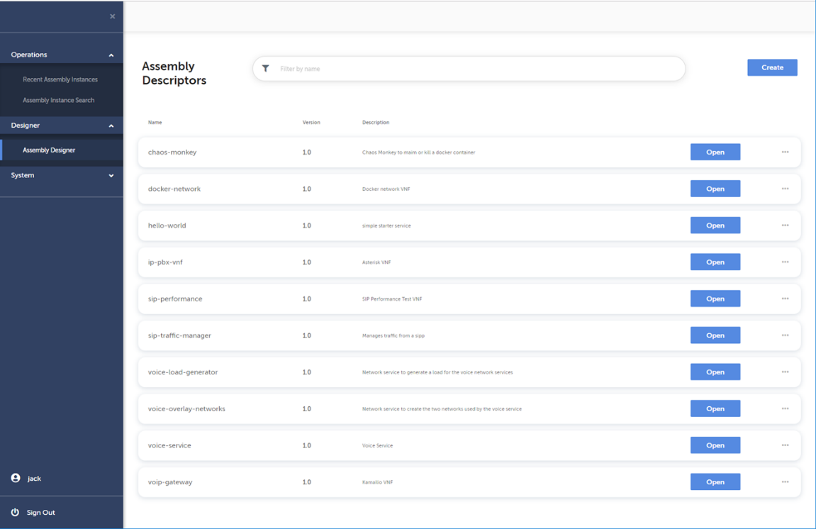
The Assembly Descriptors page lists all the Assembly Descriptors already available in TNC-O. This includes both Network Service Descriptors and VNF Descriptors.
A new Assembly Descriptor is created by clicking the Create button on the top right corner of the page. Clicking the Create button opens a dialog box (see screenshot below) allowing to enter necessary identification information associated to the Assembly Descriptor.
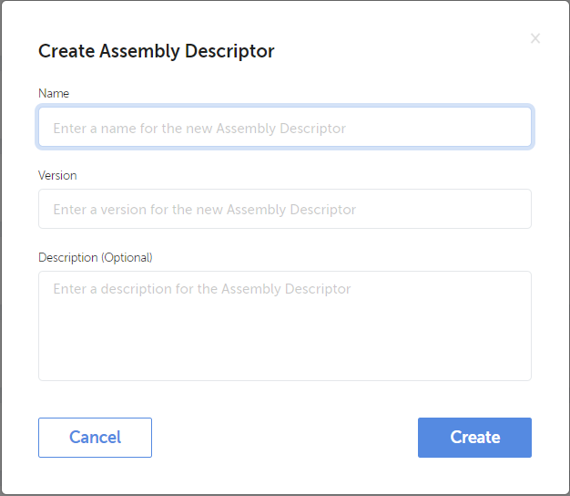
Define header information for the Assembly Descriptor according to following rules
- Name
- The name must start with a letter and must not contain spaces or colons. The name must be between 2 and 50 characters.
- Version
- The version should be numeric and can be dot separated. The version must be max 10 characters.
- Description
- The Description is a short textual description of the Assembly Descriptor. Description is an optional field and can be left empty.
- Name
After filling in the above listed fields, the creation of the new descriptor can be confirmed by clicking the Create button in the lower left corner of the dialog box.
As a result, a new Assembly Descriptor created in TNC-O environment representing the implemented network service and accessible through Assembly Descriptors page within the Service Designer.
Add elements
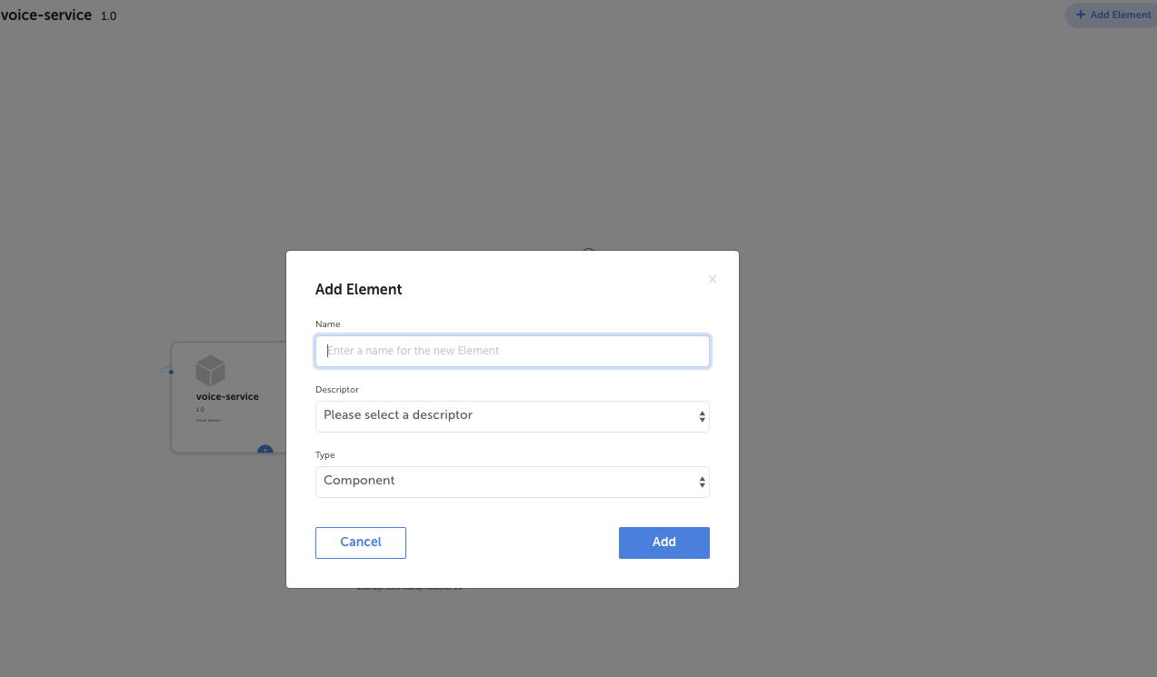
To design a Network Service, open the created Assembly instance. In order to add an element to the NS you are designing, such as a VNF, press the “Create element” button. This opens up a new dialog where you need to provide a name for the element. You also need to select the Resource Descriptor you want to use for that element, and whether it is a component or a reference. A component is embedded and part of the Assembly you are creating. A Reference is a reference to a component or Assembly outside of the NS you are creating that is required for the NS to function (e.g. a network that needs to be in place for this NS). When you press “create”, you will see the element being created in your Assembly. The picture below shows the Create Element dialog.
Add Properties
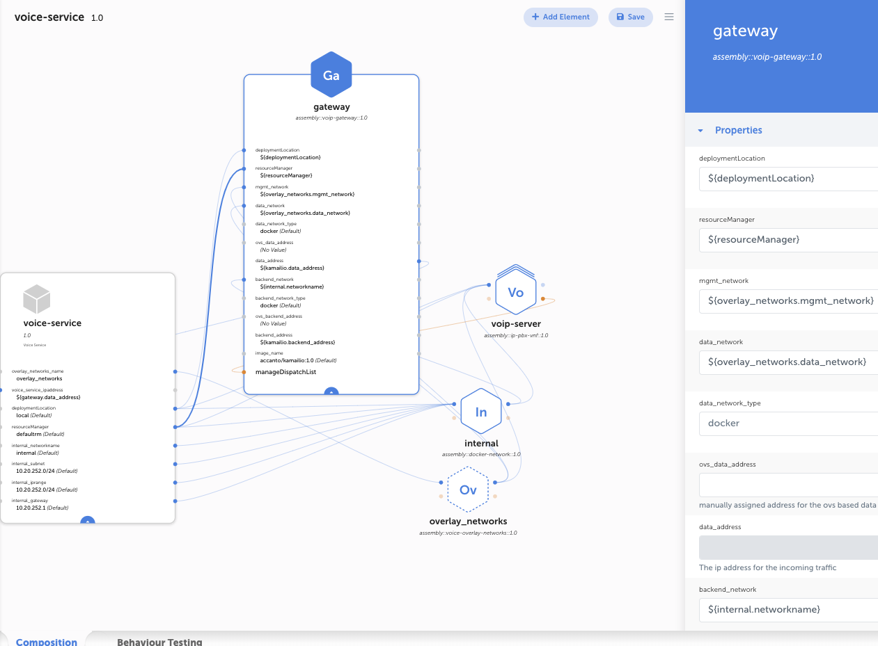
You now see the element that you created appear in the designer indicated by a hexagon. On the left you should have your top-level NS (in this example the voice-service), and on the right the element that you created. You can click on the element to see its properties.
The next thing to do is to add the Properties that are needed for the NS to be able to run. Click the top-level Network Service element and click Add property (from the right panel that appears). The picture below shows the Create Property dialog.
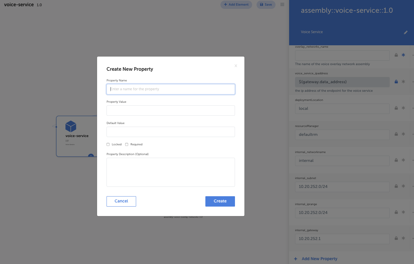
In the Create New Property dialog you give the property a name, a value, a default value, and you check whether the property is required and/or locked. You can also provide a short description of the property. Once you click Create, the property you just created will appear in the top-level NS element in the Designer.
Passing Properties
The next step is to pass in properties between the top-level NS and the VNF Element. For each property you will notice a grayed out ball on the front and at the back of that. You can pass in a property from one element to the other by simply dragging and dropping. A ball icon on the left side of the property means it is an INPUT, the ball icon on the right side means it is OUTPUT.
The picture below shows the NS and in this case the gateway element that was added with the added Resource Manager property passed between the top-level NS and the gateway and indicated by the blue highlighted line.
Metrics and Policies
TNC-O supports Load and Integrity as the standard metrics that are defined in the VNFC Descriptor. The Integrity metric is used in the Healing policy at the VNFC level to heal the VNF if it is broken. The Heal policy is designed at the VNFC level so no need to design this on the NS level.
The Load metric is used for the Scaling policy of a VNF, and can be defined in the VNF or in the NS Descriptor. In our example of a voice-service, we had already Promoted the Load metric when we designed the VNF so it becomes available on the NS level, and can be used for the Scaling policy in the next section. In a NS, you can also promote a metric if it needs to be used in a higher-level NS that uses this NS as an element.
Clustering and auto-scaling
A cluster and scaling policy can be defined in a Network Service. The Load metric is used to automatically trigger a scale in or out action. The scale policy can be based on the (promoted) metric of the VNFC/VNF itself, or from another element in the Assembly (for example scale out VNF1 based on the Load metric of VNF2).
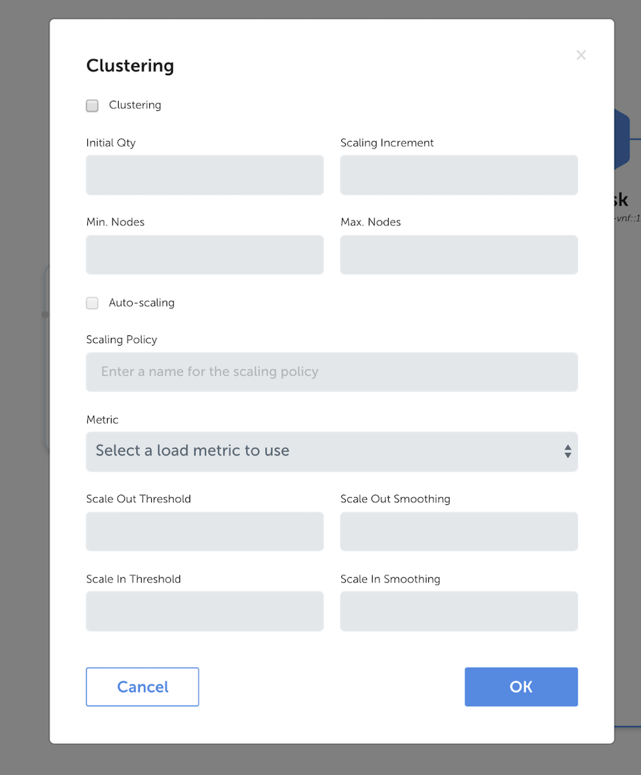
In order to design a cluster and an auto-scaling policy, you click the “…” button on the right hand panel in the Clustering section of the Properties, and select “Edit”. A new popup window appears. You first select what the cluster looks like. You define the Initial quantity that is instantiated once the VNF is instantiated, the scaling increments, and the minimum and maximum number of nodes.
You can then select the auto-scaling policy and provide a name for the policy. You select the Load metric that is to be used, and the scale-out and scale-in thresholds and smoothing periods (to avoid scaling-in and -out actions happening too frequently if thresholds are violated only once for example). The below image shows the Clustering Property window.
Operations
In the same way as with Metrics, the Operations that were defined in the VNFC Descriptor that need to be used in a higher level Network Service, need to be promoted first.
You can do this by clicking the “…” button in the Operations Property section in the right hand panel and clicking “Promote Operation”. See the image below for an example of where to promote the Operation for the Kamailio VNFC) and making that available for use in the VNF/Network Service.
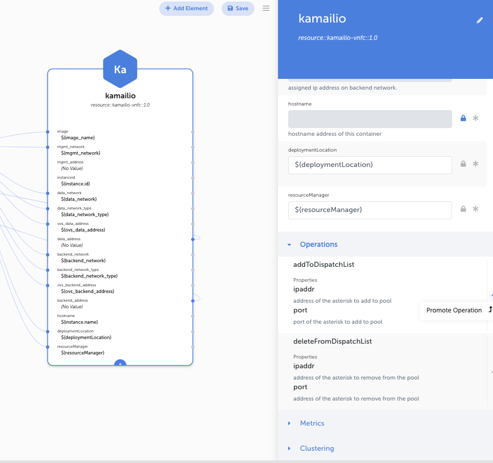
You would Promote the Operations inn the Network Service if you want to use these for Relationships in a higher-level NS.
Relationships
Relationships are very important for the Intent Engine as it uses them to determine in what order and what tasks/elements need to be established, re-established, or torn down when an Intent is carried out.
A NS can for example consist of multiple VNFs. You can add multiple VNFs by adding new elements in the NS Design and repeating the steps above. It is possible to establish relationships between the VNF elements, for example if one VNF needs to be installed before the other, or if an operation needs to be performed.
In order to establish a relationship, you can drag and drop the orange ball on the element in the design between the two VNF elements. Using the orange ball on the left of the element means a FROM relation that is then dragged to the output orange ball on the right side of the other element. Once the line is drag-and-dropped, a new screen pops up where you define the relation.
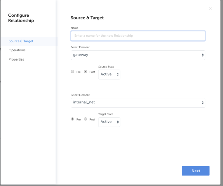
You can enter the name of the relationship, the from and to elements, whether it needs to be a pre- or post- condition, and select the source and target state of the element.
You can also select the operations that need to be carried out once the relationship is created and when it is removed. You can also provide additional properties and values. When you have filled in all the required information, press “Done” and an orange line will appear between the VNFCs that represents the relationship. On the right-hand panel the Relationships section is then also populated.