3. Topology in IT Operations
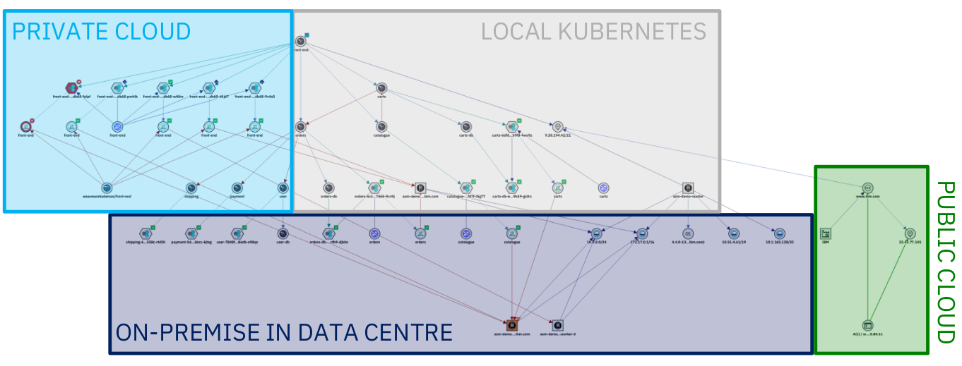
Services and applications are increasingly deployed in environments that take advantage of distributed and often virtualized infrastructure. For example, parts of a network might be cloud-based, with other connected elements contained within, or tethered to, legacy systems that exploit tried and tested on-prem capability. The result is often a highly distributed and increasingly complex hybrid network that requires an agile and dynamic resource management capability in order to leverage and exploit its rapidly evolving technologies.
The Resource Management capabilities in the Cloud Pak for AIOps provide operations teams with complete up-to-date visibility and control over dynamic infrastructure and services. They let ITOps teams query a specific networked resource, and then presents a configurable topology view with its ecosystem of relationships and states, both in real time and within a definable time window.
By visualizing complex network topologies in real-time, updated dynamically or on-demand, and allowing further investigation of events and incidents, operational efficiency is improved, problems are detected and solved faster, false alarms are reduced, and automation and collaboration between operational teams is enhanced.
Topology information adds enormous value to your IT Operations as it provides visibility into the environment and brings it to-life. With topology information its possible to:
- Visualize a seamless end-to-end view of the environment
- Create and view groups of resources that logically belong together
- Perform topology-based event correlation for events occurring within a group of related resources
The Cloud Pak for AIOps can ingest topology data from many different sources. The multiple disparate pieces of topology can then be stitched together, where it makes sense to do so, allowing to see the end-to-end environment with all the logical and physical connections represented.

Resources, Resource Groups and Applications
Resource Management has three categories of data: Resources, Resource groups, and Applications:
Resources
Resources are the lowest level of element in the system and are what is represented in topology visualizations, search experience, and APIs. They also form the basis of any topology-based event correlation. Resources are created in the system from observations of different technologies, in addition to allowing for proprietary topology data. These resources can represent a multitude of different things from the different layers of the application and infrastructure stack, for example host, vm, network interfaces, people, and locations. These resources are interconnected by relationships and their properties, which describe how the resources relate to one another. The relationship types can represent physical connections or logical connections. For example, the network interface is part-of a host; the pod runs-on a host; person owns this service. All these resources form together a complete, connected, end-to-end representation of the on-premises and cloud IT environment.
Resource groups
Resource groups are an abstraction layer on top of resources. They aim to form collections of resources that capture some business or technical context within the environment for both search and correlation purposes. It might be something simple like a namespace or geographical region, but might also capture a network layer, protocol-specific constructs (like a VLAN), or a collection of resources that represent a running service instance.
Resource groups are created either directly from topology Observers as they are observed from the various technologies ingesting topological data or can be created by defining templates that produce resource groups based on a particular criteria. The templates allow to provide business logic to define how a grouping is created. The Cloud Pak for AIOps uses templates to dynamically create groups and maintain this dynamic membership.
Applications
Applications (or also defined as ‘services’ in the Telco industry), are the highest level of abstraction. Applications are simply a collection of resource groups that best represent the customer's application stack or service in terms of its composition. For example, an application might be formed by a number of virtual machines and their hypervisors, network equipment, cloud-native services, a build pipeline, and a supporting organizational personnel. All of this can be provided to form a single holistic representation of the application, which can be used as a shared context between many different IT teams. It is important to note that while the Cloud Pak for AIOps can be seen as ‘application centric’, it is sufficiently flexible to model services or general groups-of-groups that might be needed.
These applications, when combined with resource-level event correlation and grouping mechanisms, provide customers with rapid visibility of the overall state, which allows them to prioritize root cause analysis and remediation work. They also allow operators to focus on specific sets of resources that are known to relate to a specific application, so they can exclude resources and groups of resources that are not of interest.
3.1: Topology Observers
A Topology Observer is a service that extracts resource information from a target source. Using the Observer UI, different observer jobs can be configured and run. At the time of writing this Lab, there are 34 different Observers available. The Observers are designed to connect to specific types of topology sources, such as ServiceNow, Dynatrace, or VMware vCenter.
Two of the Observers are generic: the File Observer (for ingesting file-based topology data) and the REST Observer (for ingesting topology data programmatically via an API).
In order to save resources, only a subset of Observers are enabled by default. You can see the full list of Observers and the steps to enable them by following the documentation
In this Lab, we will only leverage the File Observer, but a similar process applies to other Observers. By the end of this module, you will have created various topology Observer jobs and ingested different sets of topology data.
3.2: Creating Topology Files
This first step involves the following tasks:
- Create two sample files with topology data
- Load this data into the Cloud Pak for AIOps using the File Observer
In a real-world scenario, it is likely that you would be using a number of off-the-shelf Observers to get your topology data from your environment. It is also likely however that you would also leverage the File or REST Observers either to ingest data for which an off-the-shelf Observer doesn't exist, or to manually create relationships between Resources in your topology for which there is no import source. For example, you may wish to create connections between resources to represent logical connections or dependencies that aren't included in the original data sets. In any case, this exercise will give you the skills to use the File Observer, which will also provide you with a little more knowledge of what's going on under the covers.
In this scenario, we will have one set of topology data that represents physical infrastructure, and a second set of topology data that represents some applications running on that physical infrastructure. An example of this might be physical topology data ingested from an orchestrator, such as OpenStack, and application data, coming from an application management tool, such as AppDynamics or Instana.
Lets create a folder for the topology files in the home directory and change to this new folder. Run the following command from the Terminal window:
cd; mkdir lab-topology; cd lab-topology
Create a file called infrastructure.txt by running the following command in the Terminal window to open the text editor , copy the infrastructure topology data listed below (use the copy helper icon (top-right) for one-click copy), paste it into the text editor, click on the Save button in the text editor and close the editor window (click on the X).
gedit infrastructure.txt
V:{"_operation":"InsertReplace","uniqueId":"379177a8-0a6a-4068-817c-d6d6e870437e","matchTokens":["379177a8-0a6a-4068-817c-d6d6e870437e","router1"],"tags":["WAIOpsDemo"],"name":"router1","entityTypes":["router"],"_references":[{"_toUniqueId":"7598a194-27a0-4d0b-9c49-cbc0070c99c9","_edgeType":"uses"}]}
V:{"_operation":"InsertReplace","uniqueId":"9c1f90e0-7dc4-40d8-8721-40ea2f3af453","matchTokens":["9c1f90e0-7dc4-40d8-8721-40ea2f3af453","Intel"],"tags":["WAIOpsDemo"],"name":"Intel","entityTypes":["cpu"],"_references":[]}
V:{"_operation":"InsertReplace","uniqueId":"222-9c1f90e0-7dc4-40d8-8721-40ea2f3af453","matchTokens":["222-9c1f90e0-7dc4-40d8-8721-40ea2f3af453","AMD"],"tags":["WAIOpsDemo"],"name":"AMD","entityTypes":["cpu"],"_references":[]}
V:{"_operation":"InsertReplace","uniqueId":"7598a194-27a0-4d0b-9c49-cbc0070c99c9","matchTokens":["7598a194-27a0-4d0b-9c49-cbc0070c99c9","greatFireWallOfSecurity"],"tags":["WAIOpsDemo"],"name":"greatFireWallOfSecurity","entityTypes":["firewall"],"_references":[]}
V:{"_operation":"InsertReplace","uniqueId":"974d1788-1312-4151-8a62-73fa1854e807","matchTokens":["974d1788-1312-4151-8a62-73fa1854e807","computer1000"],"tags":["WAIOpsDemo"],"name":"computer1000","entityTypes":["computer"],"_references":[{"_toUniqueId":"379177a8-0a6a-4068-817c-d6d6e870437e","_edgeType":"connectedTo"},{"_toUniqueId":"9c1f90e0-7dc4-40d8-8721-40ea2f3af453","_edgeType":"contains"},{"_toUniqueId":"222-9c1f90e0-7dc4-40d8-8721-40ea2f3af453","_edgeType":"contains"}]}
V:{"_operation":"InsertReplace","uniqueId":"5c6f968a-2006-4b43-96b5-dd53df6b0afb","matchTokens":["5c6f968a-2006-4b43-96b5-dd53df6b0afb","steve"],"tags":["WAIOpsDemo"],"name":"steve","entityTypes":["person"],"_references":[{"_toUniqueId":"974d1788-1312-4151-8a62-73fa1854e807","_edgeType":"uses"}]}
Repeat the process and create a second file called application.txt by running the following command and use the application topology data listed below:
gedit application.txt
V:{"_operation":"InsertReplace","uniqueId":"111-379177a8-0a6a-4068-817c-d6d6e870437e","matchTokens":["111-379177a8-0a6a-4068-817c-d6d6e870437e","billing"],"tags":["WAIOpsDemo"],"name":"billing","entityTypes":["application"],"_references":[{"_toUniqueId":"111-974d1788-1312-4151-8a62-73fa1854e807","_edgeType":"runsOn"}]}
V:{"_operation":"InsertReplace","uniqueId":"111-9c1f90e0-7dc4-40d8-8721-40ea2f3af453","matchTokens":["111-9c1f90e0-7dc4-40d8-8721-40ea2f3af453","webserver"],"tags":["WAIOpsDemo"],"name":"webserver","entityTypes":["application"],"_references":[{"_toUniqueId":"111-974d1788-1312-4151-8a62-73fa1854e807","_edgeType":"runsOn"}]}
V:{"_operation":"InsertReplace","uniqueId":"111-974d1788-1312-4151-8a62-73fa1854e807","matchTokens":["111-974d1788-1312-4151-8a62-73fa1854e807","computer1000"],"tags":["WAIOpsDemo"],"name":"computer1000","entityTypes":["computer"],"_references":[]}
Confirm that you have two files created with data by running the command below:
ls -l infrastructure.txt application.txt
File Observer Format Overview
The JSON format in these two sample files is the format expected by the File Observer, and contains topology directives, one per line.
Resource properties definition:
-
_operation: A value of "InsertReplace" means that this Resource will be inserted into the topology if it does not already exist, and replace the current one if it does.
-
uniqueId: This must be a globally unique identifier for the Resource. The off-the-shelf Observers will ensure uniqueness automatically. When using the File Observer, care must be taken to ensure uniqueness, otherwise you may inadvertently overwrite existing Resources with new ones.
-
matchTokens: These values (comma separated list) are used to match the Resource against the incoming event stream. Where there is a match, the event will be associated with the Resource and be visible from the topology view.
-
tags: Tags can be handy to group Resources together, or for searching across resources that share a common tag. A resource can have multiple tags and represents a kind of group membership.
-
name: This is the primary identity of the Resource, and would normally be its most recognisable and human-readable name. The name attribute is normally the one shown in the topology viewer against a Resource.
-
entityTypes: This defines what type of Resource is being created for example: a computer or a database and will also dictate which icon it will use in the topology view.
-
references: this adds one or more edges to another resource. Each edge in the list can have some of these keywords:
- _fromUniqueId and _toUniqueId: these parameters represent the start or end points for the relationship.
- _edgeType: this parameter specifies the type of relationship this relates to, for example, its indicating a "uses" or a "contains" type of relationship. A list of default Edge types is documented here.
3.3: Creating File Observer Jobs
Log into the Cloud Pak for AIOps:
- from the burger menu in the top-left navigate to: Define → Integrations
- from the Integrations page, click on Add integration
- from the Add Integrations page, under Category click on Topology then search for File, click on the File tile and click Get started
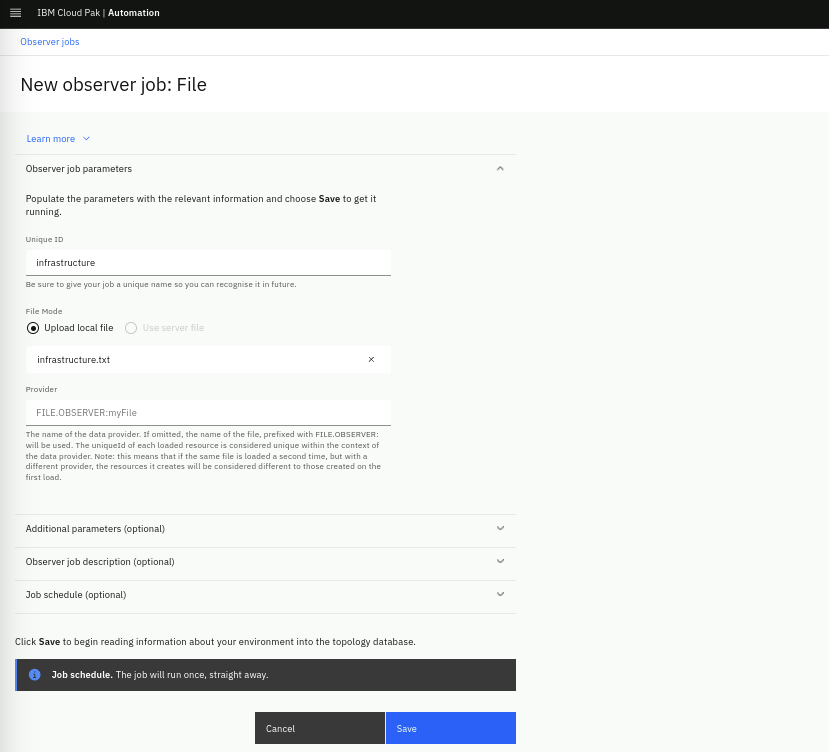
In the New observer job: File form, fill the Unique ID field as "infrastructure". Keep the File Mode as Upload local file, upload the infrastructure.txt file that you created in the previous step and click the Save button.
Make sure you upload the file under the lab-topology folder you created earlier.
The Provider field will be automatically populated when you click Save.

Now click on the Add a new job button, from the pop-up choose the File observer and repeat the process by creating a second File Observer job with the Unique ID as "application" and this time load the application.txt file.
Each job will run the moment it is saved. After you have done this, your Observer jobs screen should look like the one below. You can verify that your jobs ran successfully by confirming the Ready status for each job:

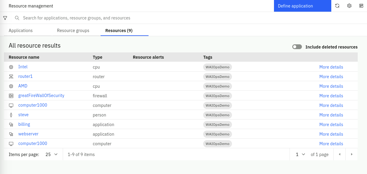
We will now search the topology for your newly added resources. From the burger menu in the top-left, navigate to: Operate → Resource management. In the Resource management page, click on the Resources tab. You should see nine resources listed:

There are two resources in the list called "computer1000". One is from the topology segment ingested from the infrastructure.txt file and the other one is from the topology segment ingested from the application.txt file. We will be merging these two Resources together in the next chapter, via a Merge Rule.
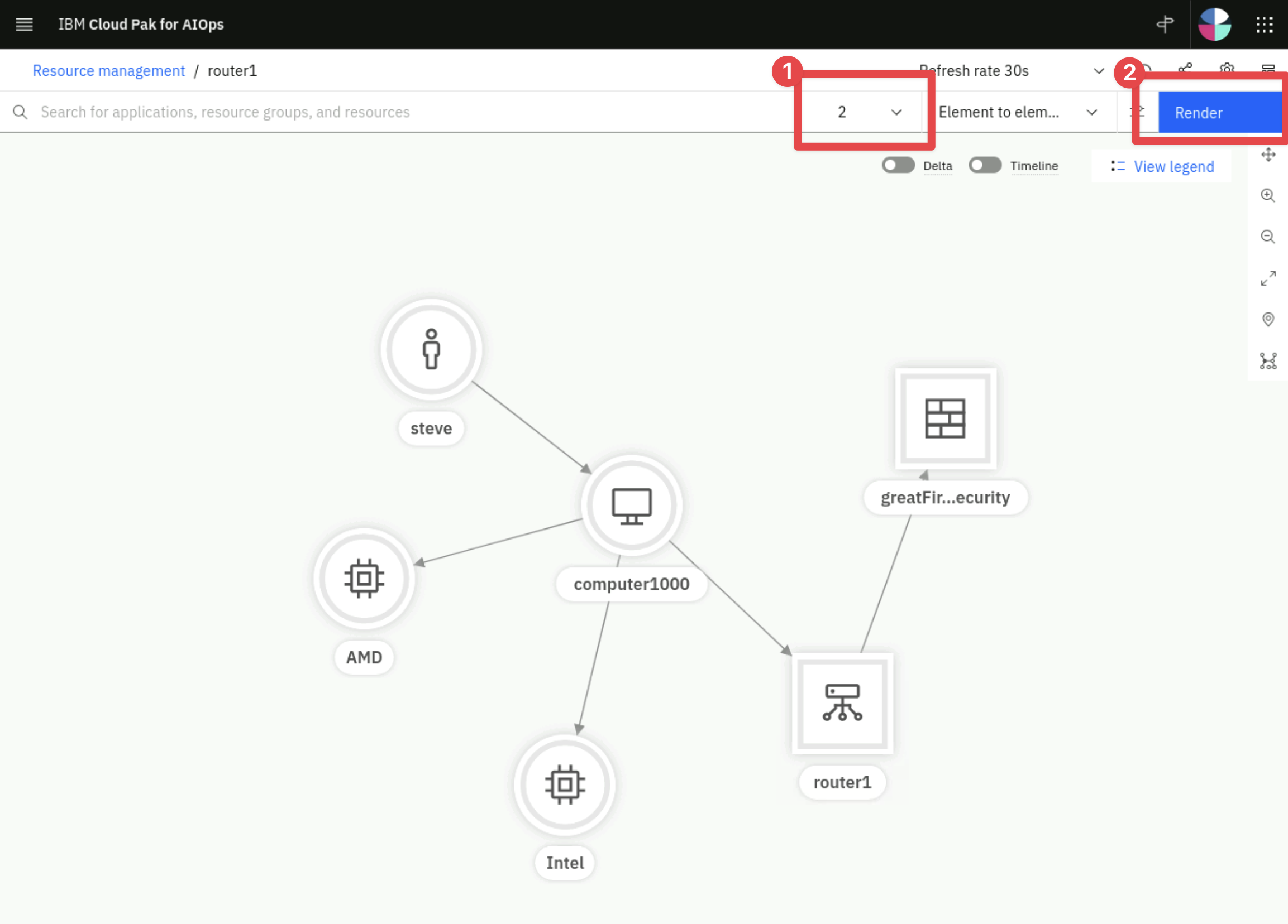
Click on router1 and it will open the topology view.
Increase the number of hops to 2 by clicking on the hops drop down list and select Render, you should see six resources as shown below:

You can click Back on your browser window and click on one of the other Resources ingested via the application job (e.g. billing). You will see a representation of the topology segment created by ingesting that file.